- #Can open putty serial with prolific usb to serial comm port serial#
- #Can open putty serial with prolific usb to serial comm port driver#
- #Can open putty serial with prolific usb to serial comm port software#
- #Can open putty serial with prolific usb to serial comm port code#
- #Can open putty serial with prolific usb to serial comm port Pc#
This routine is fast and can be used with Protothreads. sprintf converts multiple internal binary formats to a serial-format string in memory. Convert variables from internal format to a printable string, and optionally send them to the UART.In included in the library are routines to:
#Can open putty serial with prolific usb to serial comm port serial#
But for completeness, the standard i/o libary serial routines are outlined here. Instead use the ProtoThreads support explained below, and on the protothreads page. All of the standard library routines are blocking, so don't use them in a threaded environment, unless speed of execution is more important than multasking.

Connect UART transmit pin (U2TX) to white wire (default to RB10 on big board) Connect UART receive pin (U2RX) to the green wire (default to RA1 on big board) Unless you need 5 volt power for a circuit not associated with the MCU. Do NOT connect USB Vcc (red wire) to anything, Use wires to connect the the three signals below. The blue serial-USB connection is a USB cable with embedded USB/serial bridge chip with 3.3 volt logic levels.
#Can open putty serial with prolific usb to serial comm port driver#
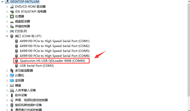
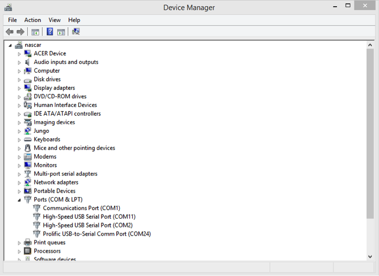
You probably want the SiLabs Chipset driver CP210x, but check the device manager. If this happens then you will need to manually download the driver from Adafruit. Look for Prolific USB-to-serial Comm Port.
#Can open putty serial with prolific usb to serial comm port Pc#
If the PC does not autoload the required driver, then the COM port will not be attached or listed. Use Control Tab.Device Manager Button.+Ports to find out which serial port is connected to the USB connection.

Connect PuTTY to whatever serial port the USB connection configures. In the PuTTY config window, choose serial connection, then click serial in the left hand panel and set the parameters. Set up PuTTY for baud-rate set in config_1_2_2.h (or after), no parity, 1 stop-bit, no flow-control. On the PC side there will be a USB connection for serial communication between the running program and the PC, which will be running PuTTY. PT_YIELD_TIME_msec(1) // may not be needed
#Can open putty serial with prolific usb to serial comm port code#
The following code could be included in the Protothreads functions to read the UART ( PT_GetSerialBuffer or PT_GetMachineBuffer). The PLIB description gives the incorrect function call.
#Can open putty serial with prolific usb to serial comm port software#
You must clear this in software using UART2ClearAllErrors(). The UART will lock up if it receives a character with a framing error or overrun error. All other slave devices discard subsequent data bytes until a new address word is received.Ĭonnections for multiple devices might look like the following: The slave device that is specified by the address word receives and processes subsequent data bytes sent by the master device. All slave devices in the communication chain receive the address word and check the slave address value The data word contains the address of a slave device and is considered the address word. The master device transmits a data word with the 9th bit set.

The protocol operates in the following sequence: If the 9th bit is cleared, the receiv ed data word is processed as data associated with the previous address/control byte. If the 9th bit is set, the data is processed as address or control information. A common scheme is to use a 9th data bit to identify whether a data byte is address or data information. In addition to the standard 8-bit mode, there is a 9-bit address mode that allows several devices to share TTL-level UART signals. A typical multi-processor communication protoc ol differentiates between data bytes and address/control bytes.

To connect two PIC32s, cross-wire TX and RX as shown below. The incoming waveform is sampled three times/bit for error detection. The UART receive block diagram shows a small FIFO and a de-serializer. The UART transmit block diagram shows that there is a small FIFO buffer and a serializer. The UART supports TTL-level RS232, considered a legacy interface, but simple and useful. It is even possible to use it in an address mode to communicate across several PIC32s. You can use it between two PIC32 processors, or from a PIC32 to a PC using a UART-USB COM port adaptor. The UART is used for comunication of serial data.


 0 kommentar(er)
